Why medical gas pipework uses EN 13348 copper
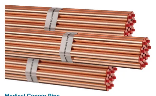
Copper is used because it is compatible with oxygen and the other medical gases, is inherently clean when correctly processed, can be jointed reliably by brazing and resists corrosion in building environments. EN 13348 goes beyond ordinary plumbing copper by controlling cleanliness, requiring degreasing, requiring the tube to be capped, and requiring the standard and diameter to be marked on the pipe so material can be identified on site.
Tecnomed supplies seamless medical copper pipe manufactured in accordance with EN 13348, in five-metre straight lengths closed with caps and marked with the norm and diameter on every pipe, together with the fittings, single and double clamps, GCu sleeves, M8 studs and washers, steel anchor clamps and clamp rail needed to complete the installation.
Degreasing, capping and storage on site
Medical tube arrives degreased and capped, and it must stay that way. Caps come off at the moment of jointing, not when the delivery is unloaded. Every open end left overnight is an invitation for dust, insects, water and site debris to enter a pipe that will later carry gas to a patient's lungs.
Store tube off the ground, under cover, away from oils, fuels and cutting fluids, and keep medical tube physically separate from ordinary plumbing copper so the two cannot be confused. Cut with a wheel cutter rather than a saw, ream the burr, and wipe the end clean without using oil-based products. Any tube contaminated with oil or grease should be rejected rather than cleaned on site.
- Keep caps in place until the joint is made
- Store off the ground, under cover, away from oil and fuel
- Segregate medical tube from ordinary plumbing copper
- Cut with a wheel cutter, ream the burr, never use oil-based cutting fluid
- Cap or plug every open end at the end of each working day
Pipe sizing and pressure drop basics
Sizing is a pressure drop calculation, not a rule of thumb. Start from the design flow for each section, applying the diversity factors used for the plant sizing, then check that the total pressure drop from the source to the most remote terminal unit stays within the allowance at that design flow. Include the losses across valves, regulators and the terminal unit itself.
Two mistakes dominate. The first is sizing on the sum of all outlets with no diversity, which produces oversized, expensive pipework. The second is sizing risers on the same basis as branches, which starves the top floor at peak. Vacuum needs particular care, because it tolerates far less pressure drop than the compressed gases and is usually the service that fails first when pipework is undersized.
Support spacing, clamps and expansion
Support spacing follows the tube diameter, with smaller tube requiring closer clamps. Clamps must hold the pipe without crushing it, and dissimilar metals must be separated so that galvanic corrosion cannot start. Tecnomed supplies single and double clamps, clamp rail for grouped runs, GCu sleeves, M8 studs and washers and steel anchor clamps for concrete and masonry fixing.
Long straight runs need a strategy for thermal movement, particularly in risers and in external or plant room sections where temperature swings are larger. Anchor at defined points and allow the tube to move between them, rather than clamping everything rigidly and letting the movement concentrate at a brazed joint. Keep pipework clear of electrical containment and label it along its route with gas identity and flow direction.
Brazing with nitrogen purge, step by step
Brazing copper in still air forms a black oxide scale inside the joint. That scale flakes off later and travels to terminal units and clinical equipment as particulate contamination, and there is no way to remove it once formed. A continuous, low-flow inert gas purge through the pipe during heating displaces the air and prevents the scale from forming in the first place.
The technique is not difficult but must be applied to every joint without exception, including the last connection made in a ceiling void at the end of a long shift. Purge flow should be enough to displace the air but gentle enough not to disturb the molten filler. Verify by cutting open a test joint at the start of the works and inspecting the bore, and keep that sample as evidence in the project file.
- Cut square, ream and clean the tube end and the fitting socket
- Assemble the joint and establish a low-flow inert purge through the pipe
- Confirm purge gas is flowing out of the far end before applying heat
- Heat the joint evenly and apply the correct filler for medical gas service
- Maintain the purge until the joint has cooled
- Cap the open end again before moving to the next joint
- Inspect a sample joint bore at the start of the works and retain it as evidence
Pressure testing, purging and particulate checks
Testing follows the EN ISO 7396-1 sequence. The installed pipework is pressure tested for leakage and mechanical integrity, usually in sections as the work proceeds so that faults are found while the route is still accessible. Cross connection testing then proves, outlet by outlet, that each terminal unit delivers only its own gas.
The system is then purged and checked for particulates, and the gas at the outlet is verified for identity and quality before flow and pressure performance are tested at the design condition. Under HTM 02-01, the work is carried out under a permit to work and released for clinical use by the quality controller, with the results recorded as the validation file for the installation.
Labelling and as-built documentation
Pipework must be labelled with gas identity and flow direction at intervals along its route, at both sides of every wall and floor penetration, and adjacent to every valve. Labels are for the engineer who opens the ceiling in fifteen years, and they are the cheapest safety measure in the entire installation.
As-built documentation should record the actual routes, valve positions and zone boundaries, the terminal unit standard used in each area, the material certificates for the tube, the brazing records, the complete test results and the alarm point schedule. Handing over an accurate set is what allows the hospital to maintain, modify and extend the system safely for the rest of its life.
Frequently asked questions
Can ordinary plumbing copper be used for medical gases?
No. Medical gas pipework requires tube to EN 13348, which controls cleanliness, requires degreasing and capping and is marked with the standard and diameter. Ordinary plumbing copper may carry oil or drawing residues and has no such marking, so it cannot be verified as suitable on site.
Why braze under a nitrogen purge?
Heating copper in air produces internal oxide scale that later breaks away and contaminates terminal units and clinical equipment. A continuous inert gas purge through the pipe during brazing prevents the scale forming. It must be applied to every joint, since one unpurged joint can contaminate a whole branch.
How is medical gas pipe sized?
By pressure drop at design flow to the most remote terminal unit, using the same diversity factors as the plant sizing and including losses across valves, regulators and the terminal unit. Vacuum in particular needs careful sizing because it tolerates much less pressure drop than the compressed gases.
What documentation should the installer hand over?
Material certificates for the tube, brazing and purge records, sectional and final pressure test results, cross connection test records for every outlet, particulate and gas quality results, alarm verification records, labelled as-built drawings and the quality control release before clinical use.