Planning the pendant position early in the MEP design
The pendant flange position is a structural and services decision, not a furniture decision. It has to be agreed before the slab reinforcement is detailed, before the ceiling grid is set out and before the medical gas risers are routed. Late changes mean core drilling into a designed slab, or a compromise position that the clinical team will live with badly for twenty years.
Start from the bed or table position agreed with the clinical team, draw the working envelope of the chosen arm configuration around it, and check the envelope against the surgical light envelope and the ceiling services. Only then fix the flange. Issue a reflected ceiling plan showing pendant flanges, light mounts, diffusers, sprinkler heads and rail positions as one coordinated drawing.
Structural ceiling reinforcement and anchor plates
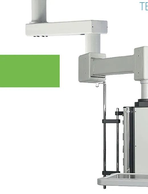
The pendant transmits both a vertical load and a substantial overturning moment into the structure, because the equipment load acts at the end of an extended arm. Tecnomed pendants carry 90 kg as standard and up to 180 kg in customised builds, and the structural design must be based on the loaded, fully extended condition, with the appropriate safety factor applied by the structural engineer.
In new build, the usual solution is a cast-in anchor plate or a reinforcement frame positioned before the slab is poured. In refurbishment, a steel spreader frame fixed back to the structural slab with tested anchors is common, with the connection designed by an engineer who has seen the actual slab construction. Suspended ceiling grids never carry pendants; the pendant passes through the ceiling and connects to structure above.
- Design load: pendant self-weight plus full equipment load at maximum arm extension
- Cast-in anchor plate or reinforcement frame for new build slabs
- Engineered steel spreader frame with tested anchors for retrofit
- Anchor position surveyed and recorded before the ceiling is closed
- Structural sign-off held in the project file for handover
Ceiling height and clearance requirements
Two dimensions matter: the structural slab to finished floor height, which determines the column length available, and the finished ceiling height, which determines the clearance between the service head and the floor. Too little height and the head sits in the way of staff and doors; too much and outlets are out of comfortable reach, particularly for shorter staff.
Check the swept path, not just the static position. The head must clear the bed in its highest position, any overhead imaging equipment, the surgical light in all its positions, and the door head if the arm can swing toward the entrance. Where the ceiling void is shallow, the pendant column and its service risers may not fit, and that constraint should be discovered on a section drawing rather than on site.
Routing medical gas, power and data to the ceiling
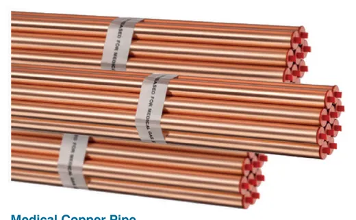
Every service arrives at the flange. Medical gas copper to EN 13348 is brazed under a nitrogen purge, supported at the correct clamp spacing and pressure tested before the ceiling is closed. Power comes from two sources, normal mains and the uninterruptible supply, with the UPS circuits identified so that the correct sockets on the head are fed from the correct board.
Data, video and nurse call cabling should be drawn into the arm in a separate route from the mains cabling, and left with enough service loop at the flange for the head to reach every position in its envelope without straining a cable. Label everything at the flange during installation; identifying an unmarked cable after the ceiling tiles are in place is a needlessly expensive exercise.
Coordination with lighting, HVAC and sprinklers
Operating theatres are the hardest case, because the laminar flow canopy, the surgical light mounts, the pendant flanges and the sprinkler heads all compete for the same ceiling. Any object inside a laminar flow field disturbs it, so pendant positions and the height of the head relative to the canopy edge must be agreed with the ventilation designer.
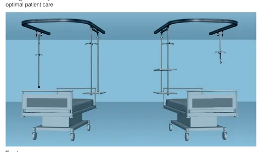
In intensive care the conflicts are usually with supply and extract diffusers, ceiling rails and lighting. Sprinkler heads need their own clearance to the deflector, and moving one after installation is a wet and disruptive job. A single coordinated reflected ceiling plan, reviewed by the structural, mechanical, electrical and clinical teams together, prevents almost all of these clashes.
Commissioning, load testing and handover
Commissioning covers three domains. Structurally, the pendant is load tested at the design load with the arms extended, and the brakes are checked to hold position under that load. Mechanically, every joint is exercised through its full rotation to confirm there are no clashes and that the head returns to its parked position cleanly.
For services, the medical gas outlets are tested to EN ISO 7396-1 for leakage, cross connection, flow and identification, and the electrical circuits are verified including earth continuity and equipotential bonding at the head. Handover should include the structural sign-off, the gas test certificates, the electrical verification, and operating and maintenance instructions for the brakes and, where fitted, the motorized column.
Pre-installation checklist
Run through this list before the installation crew is mobilised, and confirm each item in writing rather than by assumption. Every point on it has stopped a pendant installation somewhere, usually on the day the crew arrived on site and discovered that the anchor plate was in the wrong place or the pipework had never been pressure tested.
Hold a short site walk with the installer, the mechanical contractor and the clinical lead a fortnight before the works. Standing in the room together resolves questions about flange position, service loops and access equipment far faster than an exchange of emails, and it is the last practical opportunity to move anything before the ceiling is closed.
- Flange positions agreed with the clinical team and fixed on a coordinated reflected ceiling plan
- Structural reinforcement or anchor plate installed, surveyed and signed off
- Slab to finished ceiling dimension confirmed against the ordered column length
- Working envelope checked against surgical light, imaging equipment and doors
- Medical gas pipework brazed, purged, pressure tested and capped at the flange
- Normal and uninterruptible power circuits pulled, identified and terminated
- Data, video and nurse call cabling pulled with adequate service loop
- Sprinkler, diffuser and ceiling rail positions confirmed clear of the envelope
- Access equipment and a clean, dry room available for the installation crew
Frequently asked questions
Can a medical pendant be fixed to a suspended ceiling?
No. A suspended ceiling grid cannot carry the vertical load and overturning moment a pendant applies. The pendant must connect to the structural slab or to an engineered steel frame fixed back to structure, and pass through the suspended ceiling with a trim collar.
What ceiling height does a pendant need?
Enough for the column length plus the service head to sit at a comfortable working height with clearance above the highest bed position. Check the slab to finished floor dimension and the finished ceiling height separately, and verify the swept path against doors, lights and imaging equipment on a section drawing.
What load should the ceiling fixing be designed for?
The pendant self-weight plus the full equipment load with the arms at maximum extension, with the safety factor applied by the structural engineer. Tecnomed pendants are rated at 90 kg as standard and up to 180 kg in customised builds, so state the required capacity before the structural design is fixed.
What tests are done at handover?
A structural load test with the arms extended and the brakes holding, a full mechanical exercise of every joint, medical gas testing to EN ISO 7396-1 covering leakage, cross connection, flow and identification, and electrical verification including earth continuity and equipotential bonding at the service head.