What the vacuum plant has to deliver at each terminal unit
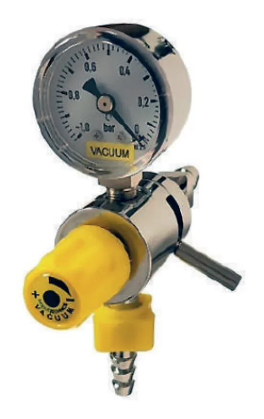
Medical vacuum is specified as a flow of free air at a stated vacuum level measured at the terminal unit. EN ISO 7396-1 sets the nominal design condition, and vacuum regulators at the bedside are set within that envelope. Tecnomed vacuum regulators adjust from around minus 250 mbar up to a maximum of minus 1000 mbar, with paediatric scaling available where lower suction is required.
Sizing is therefore not simply a matter of pump displacement. The plant must be able to hold the design vacuum at the furthest and highest terminal unit while the pipeline carries the full design flow. Pipe sizing and vacuum level go together: an undersized riser will starve the top floor even when the plant itself has ample capacity.
Design flow, diversity factors and department profiles
Every department has its own usage profile. Operating theatres and intensive care units use vacuum heavily and simultaneously, so their diversity factor is high, sometimes approaching one for theatres in use. General wards have many outlets but few in use at any moment, so their diversity factor is low. Recovery, emergency, delivery suites and endoscopy sit between the two.
Build the calculation department by department rather than applying a single factor to the whole hospital. List outlet counts per area, assign a flow per outlet in use and a diversity factor, and keep the assumptions visible in the design file. When the hospital later adds beds, the calculation can be updated instead of redone, and the tender panel can see exactly what was assumed.
- Operating theatres and ICU: high simultaneous use, high diversity factor
- Recovery, emergency and delivery rooms: moderate simultaneous use
- General wards and outpatient areas: many outlets, low simultaneous use
- Add a leakage allowance for the installed pipework and terminal units
- Add a documented allowance for planned future expansion
Worked example: calculating total free air flow
Take a hospital with six theatres, twenty intensive care beds, and two hundred ward beds each with one vacuum outlet. Applying a high diversity to theatres and ICU and a low diversity to wards gives three department subtotals of free air flow. Summing them gives the clinical demand. A leakage allowance is then added as a percentage of the total, and a future expansion allowance as a fixed block.
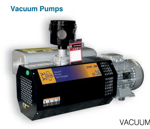
The result is the design free air flow for the plant. Pumps are selected against this figure at the design vacuum, not at their headline free-air rating, because displacement falls as vacuum deepens. Always read the pump curve at the operating vacuum. Tecnomed publishes performance data across its TEC025 to TEC305 vacuum pump range so selection can be checked at the real duty point rather than at the catalogue maximum.
Choosing pump type, duplex or triplex configuration
Rotary vane and claw pumps dominate hospital vacuum service. Oil-lubricated rotary vane pumps are compact and tolerant, with oil and exhaust filtration to manage. Dry claw pumps avoid oil entirely and reduce servicing, but cost more at purchase. Both are acceptable provided the exhaust is discharged safely outside, clear of air intakes and windows.
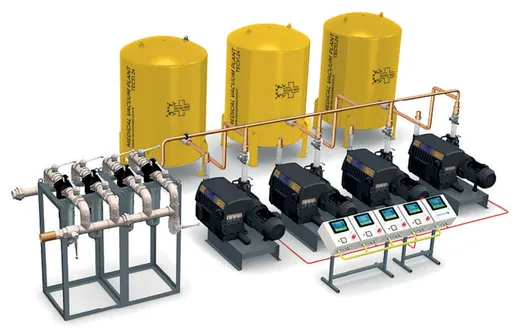
Duplex sets with two pumps suit small hospitals where one pump can carry the full design flow. Triplex sets are the usual choice for medium and large hospitals, because three pumps sized at half the design flow each let two run at peak while the third is serviced. Tecnomed builds triplex, rack system and tank-over medical vacuum plants, so the same capacity can be delivered in the footprint the plant room actually offers.
Receiver tank, bacteria filters and control panel selection
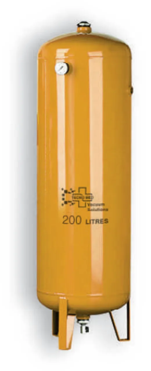
The receiver tank buffers short peaks and limits pump starts per hour, which is what protects motor life. Tank volume should be matched to the pump control strategy: fixed-speed pumps need a larger receiver than variable-speed sets. Tank-over plants mount the pumps directly on a horizontal receiver and save floor area, which is often the deciding factor in a retrofit.
Bacteria filter groups sit upstream of the pumps to protect them and the exhaust from contamination, and are installed in duplex so one can be changed without stopping the plant. The control panel should rotate duty between pumps to equalise running hours, stage additional pumps in on falling vacuum, and report running status, faults and low vacuum to the alarm system. Tecnomed PLC control panels handle sequencing and provide those signals.
Redundancy and standby requirements
The governing rule is simple: the plant must still meet the full design flow with the largest single pump unavailable. That is the reason a triplex set is sized at half duty per pump rather than a third. Apply the same thinking to the electrical supply, which should come from an essential circuit so vacuum survives a mains failure, and to filtration, which should be duplexed.
Isolation matters as much as capacity. Each pump needs its own isolating valve so it can be removed without draining the system, and the receiver needs a drain and a service bypass arrangement. HTM 02-01 also expects a documented maintenance regime with recorded running hours, filter changes and oil changes where applicable.
Common sizing mistakes
The two classic errors pull in opposite directions. Summing every outlet with no diversity produces a plant that is two or three times too large, short-cycles, wears its pumps and wastes energy for decades. Ignoring leakage and future expansion produces a plant that cannot hold vacuum on a busy morning within five years of handover. Both come from skipping the department-by-department calculation.
The list below covers the faults that show up most often when an installed plant is investigated. Almost all of them are cheap to avoid at design stage and expensive to correct afterwards, because the plant room is usually the most congested space in the building and the pipework is buried in shafts and ceilings by the time the problem becomes obvious.
- Reading pump capacity from the free-air rating instead of the curve at design vacuum
- Sizing the plant correctly but undersizing risers and branch pipework
- Omitting the leakage allowance for terminal units and long pipe runs
- Fitting a receiver too small for the number of starts per hour
- Placing the exhaust discharge near a fresh air intake or an openable window
Frequently asked questions
What vacuum level should the plant hold at the terminal unit?
The design vacuum required by EN ISO 7396-1 at the terminal unit, maintained at full design flow at the most remote outlet. Bedside vacuum regulators then set the clinical level; Tecnomed regulators adjust from about minus 250 mbar to minus 1000 mbar, with a paediatric option for lower suction.
Duplex or triplex: how do I decide?
Decide by what happens when one pump is out of service. If a single pump can carry the whole design flow, a duplex set is sufficient. If it cannot, use a triplex set with each pump at roughly half duty, so two pumps cover peak demand while the third is serviced or has failed.
Where should the vacuum exhaust discharge?
Outside the building, at a safe height, away from air intakes, windows and pedestrian areas, with bacteria filtration upstream of the pumps. The discharge route should be independently supported and sized so that back pressure does not reduce pump performance at the design duty.
How much spare capacity should be allowed for future expansion?
Enough to cover known plans plus a documented margin, agreed with the hospital rather than assumed. Carrying an explicit expansion block in the calculation is better than inflating diversity factors, because it keeps the real clinical demand visible when the plant is reassessed later.