What a medical gas manifold does in a hospital pipeline
A manifold is the source of supply for gases that a hospital buys in cylinders rather than generating on site: nitrous oxide, carbon dioxide, nitrogen, and oxygen or medical air where no plant is installed. It takes gas at cylinder pressure, typically up to 200 bar, and delivers a stable pipeline pressure of around 4 bar for patient gases or 7 bar for surgical air, continuously and without operator intervention.
EN ISO 7396-1 and HTM 02-01 treat the manifold as a complete supply system rather than a regulator. That means a primary supply, a secondary supply and a reserve, each able to meet the design flow on its own, plus monitoring that tells the estates team what the system is doing. A Tecnomed automatic manifold supply unit packages these functions into one wall-mounted assembly with its own alarm control unit.
Main components: cylinder banks, ramps, regulators and control panel
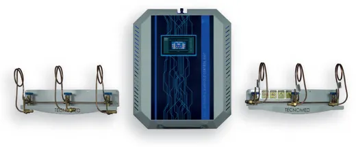
Two cylinder banks sit either side of the manifold, each built from a header pipe and a ramp carrying one to six cylinder connections. Flexible copper pigtails or high-pressure hoses link each cylinder to the ramp through a non-return valve, so a single cylinder can be changed while the rest of the bank stays in service. Isolation valves let a whole bank be shut off for maintenance.
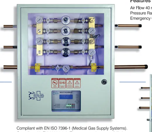
Downstream of each bank sits a high-pressure regulator that drops cylinder pressure to an intermediate value. The two intermediate lines meet at the changeover section, where a second-stage regulator sets the final pipeline pressure. A control panel carries the gauges, the changeover indication and the electrical outputs to the alarm unit. Tecnomed supplies Deluxe, Vexillum and Junior variants of this assembly with matching DMA, VMA, TSA and OSA alarm control units.
- Cylinder ramps for 1 to 6 cylinders per bank, extendable as consumption grows
- Flexible copper pipe or high-pressure hose cylinder connections with non-return valves
- First-stage high-pressure regulators on each bank, second-stage line regulator after changeover
- Relief valve and evacuation valve for safe venting during cylinder change
- Alarm control unit with volt-free contacts for the BMS
How automatic changeover between duty and standby banks works
Changeover is driven by pressure, not by a timer. The duty bank regulator is set marginally higher than the standby bank regulator, so all flow naturally comes from the duty side. As its cylinders empty, the delivered pressure falls. The moment it drops below the standby setting, gas begins to flow from the standby bank instead. The transition is gradual and the pipeline never sees a pressure step that clinical equipment would notice.
Fully automatic units add a control head that senses the transfer, reverses the duty and standby roles once the empty bank is replenished, and drives an indicator on the front panel. This is why the sequence needs no operator: the empty bank simply becomes the new standby when fresh cylinders are fitted. Semi-automatic designs perform the same pressure transfer but require the duty selector to be reset by hand.
Reserve supply, pressure stages and alarm signals
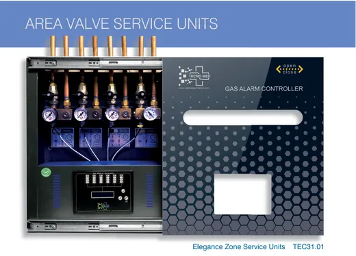
EN ISO 7396-1 expects three levels of supply. The duty bank is the primary supply, the standby bank is the secondary supply, and a separate reserve, often an emergency cylinder group or a NIST emergency inlet on the floor regulator panel, covers failure of both. Pressure is reduced in stages rather than in one step, which keeps regulator creep small and gives the second stage a stable inlet to work from.
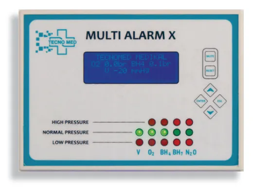
Three signals matter to the hospital. A changeover signal says the duty bank has emptied and cylinders need replacing. A low line pressure signal says the pipeline itself is below its clinical limit. A high pressure signal warns of regulator failure. All three are high-priority indications and must reach a location that is permanently staffed. Tecnomed alarm control units provide these contacts and the Multi Alarm X panel can pass them to the BMS over RS485 Modbus.
Sizing the cylinder banks for your consumption
Sizing starts with two figures: peak design flow and daily consumption. Peak flow sets the regulator and pipe size, because the manifold has to hold pipeline pressure when every terminal unit in the busiest department is in use. Daily consumption sets the number of cylinders per bank, because each bank should run for a sensible period between changes, usually at least one working day and preferably a full weekend.
Convert cylinder contents to free gas volume, divide by daily consumption, and compare the result with how often your supplier can deliver. A 6+6 bank that empties twice a day is a staffing problem, not a technical one. Where consumption is genuinely large, an on-site PSA oxygen generator or a liquid oxygen installation is usually the better answer, with the manifold retained as the reserve supply.
Installation, ventilation, safety and maintenance
The manifold room must be dedicated, lockable, fire-rated and mechanically or naturally ventilated at high and low level, with cylinders restrained against falling and full and empty stock clearly separated. Oxygen and nitrous oxide rooms need signage prohibiting oil, grease and smoking. Relief valve discharges and the evacuation valve should be piped outside to a safe location away from air intakes.
All pipework between the manifold and the first isolating valve is medical-grade copper to EN 13348, brazed under a nitrogen purge and degreased for oxygen service. Electrical supply to the control panel should come from an essential circuit, so changeover indication and alarms survive a mains failure. Commissioning follows the EN ISO 7396-1 sequence of leak, cross-connection, purity and performance testing before any clinical use.
Most manifold faults trace back to three things: worn pigtail sealing washers, drifting regulators and neglected relief valves. A short monthly walk-round catches all three. Record the pressures on both banks, confirm which side is duty, listen for leaks at the ramps and check that the changeover indication matches reality. Annual service should include regulator overhaul or replacement of wearing parts and a functional test of every alarm condition.
- Changeover happens too early: standby regulator set too close to the duty setting
- Both banks drain together: non-return valve leaking on one ramp
- Line pressure creeps up at night: second-stage regulator seat contaminated or worn
- Persistent low pressure alarm at peak: bank or pipe sized below true peak flow
- Frost on a pigtail: high flow through a partially closed cylinder valve
Frequently asked questions
What is the difference between an automatic and a semi-automatic manifold?
Both transfer supply from the duty bank to the standby bank on falling pressure. A fully automatic manifold then reassigns duty and standby roles by itself once the empty cylinders are replaced, so no operator action is needed. A semi-automatic unit requires staff to reset the duty selector manually after every changeover.
How many cylinders should each bank have?
Enough to hold pipeline pressure at peak flow and to run for at least one working day, ideally a full weekend. Tecnomed cylinder ramps are supplied for one to six cylinders per side and can be extended, so the bank can grow with the hospital rather than being replaced.
Does a manifold still need a reserve supply if it changes over automatically?
Yes. EN ISO 7396-1 treats the duty and standby banks as the primary and secondary supplies. A third, independent reserve is still required to cover failure of both, commonly an emergency cylinder group or an emergency NIST or AFNOR inlet on the area regulator panel.
Which alarms must a manifold provide?
As a minimum, a changeover or low contents signal at the plant, plus high and low line pressure alarms at a continuously staffed location. Tecnomed alarm control units deliver these signals and can be linked to the Multi Alarm X panel for digital display and Modbus reporting to the building management system.